Fiber Amplifiers – a Technology for Many Applications, Part 2: Various Technical Issues
Author: Rüdiger Paschotta, RP Photonics AG
(This article appeared in similar form in Laser Technik Journal 6 (5), 48 (2009). See also Part 1 – Introduction and Part 3 – Examples of Fiber Amplifier Designs.)
Abstract: Fiber amplifiers are technology with vary variants, covering an ever expanding area of applications. Part 1 of this series gave an introduction to the technology of fiber amplifiers. Part 2 discusses various technical issues. Part 3 will address example cases.
Stark Level Manifolds and Quasi-three-level Behavior
Various interesting properties of active fibers can be understood by considering details of the energy levels of the rare earth ions. The energy level schemes exhibit so-called Stark level manifolds. Each such manifold contains some number of Stark levels with slightly different energies. Due to the inhomogeneous nature of the glass matrix, the optical transitions are “smeared out”, so that it is not possible to clearly resolve separate Stark levels (unless at very low temperatures). Within each Stark level manifold, fast phonon-mediated transitions between the sub-levels rapidly establish a thermal equilibrium, where the higher sub-levels have a somewhat lower occupation probability than the lower ones.
An amplifier may work with just two Stark level manifolds. In ytterbium (Yb3+) amplifiers, for example, ions are pumped from the ground state manifold to an excited manifold, and the amplifier transition brings the ions back from there to the higher sub-levels of the ground state manifold. There is some reabsorption of signal light because even the higher-lying sublevels of the ground state manifold have some population. Nevertheless, for sufficiently high pump intensities a positive net gain is possible on the longer-wavelength transitions, where the reabsorption is comparatively weak. For low pump powers, however, absorption dominates, and the signal is attenuated by the device.
This so-called quasi-three-level behavior occurs in most fiber amplifiers. Notable exceptions are neodymium (Nd3+) amplifiers operating in the 1-μm or 1.3-μm regime. In that case, the lower laser levels belong to higher-lying Stark level manifolds, from where ions are quickly brought to the ground state manifold via multi-phonon emission. As a consequence, there is essentially no signal reabsorption; the unpumped amplifier causes hardly any attenuation of the signal, and positive net gain is achieved even for low pump powers. The price to pay, however, is that the pump photon energy must be substantially higher than the signal photon energy. Therefore, the power conversion efficiency is reduced. Figure 1 shows energy level schemes of several laser-active ions and indicates some important pump and amplifier transitions.

Each horizontal line indicates a whole Stark level manifold, containing multiple Stark levels. The level energies and transition wavelengths somewhat depend on the host material. The dashed lines indicate fast non-radiative multi-phonon transitions.
Small-signal Gain, Gain Efficiency and Gain Bandwidth
If the signal is very weak, and if no significant ASE (see below) occurs, the level populations are essentially determined by the balance of pumping and spontaneous emission. The pump power is required just for maintaining the upper-level population in the presence of spontaneous emission. In simple cases, the small-signal gain measured in dB is proportional to the absorbed pump power.
The “gain efficiency” in dB/mW is the small-signal gain per unit pump power. It depends on various factors, including the efficiency of the pumping process, the (wavelength-dependent) transition cross-sections for the signal and the lifetime of the upper level of the amplifier transition, and also the mode area of the signal light and its overlap with the doped fiber core. A high gain efficiency is obtained in fibers with small mode areas: easily several dB/mW or even >10 dB/mW. Note that a high gain efficiency is not always desirable; to the contrary, it can cause strong ASE (see below) and thus limit the amount of energy which can be stored in the amplifier.
The amplification works for some range of signal wavelengths. The width of that range, called the gain bandwidth, depends not only on the type of ion and the glass material (influencing the energy spread within the Stark level manifolds), but (at least for quasi-three-level systems) also on the degree of excitation of the upper level. Both the width and peak position of the gain spectrum may shift substantially e.g. when the pump power is increased. This is because the balance of stimulated emission and reabsorption, which have different wavelength dependencies, is changed.
Gain Saturation
When the signal (or ASE, see below) becomes strong, stimulated emission depletes the population in the upper level and in that way reduces (saturates) the gain. The most efficient transfer of pump power to signal power occurs in the strongly saturated regime because this maximizes useful stimulated emission by the signal while reducing spontaneous emission and ASE.
The (local) signal power level where saturation becomes important in the steady state is called the saturation power. It depends on the transition cross-sections and the upper-state lifetime of the material, and is also proportional to the signal mode area.
In some cases, an amplifier is saturated by a short signal pulse. In that case, the strength of saturation is determined by the signal pulse energy, not the peak power. Saturation becomes strong for energies above the so-called saturation energy, which depends on cross-sections and the mode area, but not on the upper-state lifetime.
Amplified Spontaneous Emission
As soon as the upper level is populated, some amount of spontaneous emission occurs. Only a small amount of the emitted power propagates along the fiber core, but that part can be amplified in the same way as the signal, at least within some wavelength range. When the gain becomes high (e.g. >30 dB), this amplified spontaneous emission (ASE) can become strong –- possibly even stronger than the signal. That effect is normally unwanted.
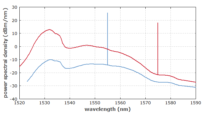
A solution for high-gain amplifiers can be a design with multiple amplifier stages, between which ASE is filtered out. Fig. 2 shows results of a simulation for an erbium-doped fiber amplifier. A 1555-nm signal (blue curve) is strongly amplified, and ASE is well suppressed. For an equally strong 1575-nm input signal, the gain is lower, gain saturation is weaker, and ASE becomes stronger.

The simulation has been done with the software RP Fiber Power.
Energy Storage
An amplifier may be pumped for a while to store a certain amount of energy, which is then extracted by a short signal pulse. The maximum stored energy is often limited by the onset of ASE when the gain becomes too high. Therefore, a large mode area is beneficial, as it decreases the gain efficiency. Another factor is the upper-state lifetime, which determines the energy loss via spontaneous emission (even without amplification).
Large mode area fiber amplifiers can be utilized for pulse energies of multiple millijoules. Extraction of such high energies, however, requires relatively long pulse durations (typically microseconds), as otherwise the peak power gets too high.
Nonlinear Effects and Damage
Particularly when a fiber amplifier is used for generating signal pulses with high energy and peak power, various kinds of nonlinear effects can occur, which are often detrimental. Although the often used silica glass material has an intrinsically low nonlinearity, nonlinear effects in fibers can become strong even at moderate peak power levels due to the tight transverse confinement of light and the often substantial amplifier length. Note that particularly high-power amplifiers often have a length of many meters, partly because cladding pumping (see part 1) is used, and this requires a longer length of fiber for efficiently absorbing the pump light.
The Kerr nonlinearity of the glass can lead to self-phase modulation of the signal pulses. This can be very disturbing for the amplification of ultrashort pulses, although that effect may be irrelevant for some laser material processing applications. For single-frequency (or other narrow-band) amplifiers, stimulated Brillouin scattering (SBS) can occur, possibly causing much of the signal light to be reflected back. Even for broader signal bandwidth, but only at higher power levels, stimulated Raman scattering (SRS) can transfer a lot of signal power into unwanted new wavelength components.
At peak powers of more than a few megawatts, the Kerr nonlinearity can cause self-focusing of the light, leading to a collapse of the beam profile and thus to further increased intensities and to permanent damage. Remarkably, the power limit set by self-focusing does not depend on the mode area.
Essentially all nonlinear effects except for self-focusing can be reduced by increasing the mode area of the fiber. Whereas a standard single-mode fiber has a mode area of the order of 100 μm2, large mode area fibers can have several thousand μm2 and correspondingly weaker nonlinear effects. Unfortunately, there are limits to that strategy, at least for single-mode propagation, as is desirable for high beam quality of the output. A fundamental problem is that a fiber mode is stabilized by two counter-acting effects, namely diffraction and waveguiding, and that this balance becomes weaker and weaker for larger mode areas. Any additional effect, caused by bending or imperfections in the fiber, for example, may then disturb the mode and cause extra power losses. Certain design strategies allow one to obtain large mode area fibers with comparatively high robustness (low bend sensitivity etc.), but there appear to be fundamental limitations.
Sensitivity to Reflections
A common difficulty, particularly with high-gain fiber amplifiers, is the high sensitivity to any back-reflected signal light. This is because that light can again be amplified and may, e.g., destroy the seed source at the fiber input, or at least saturate the amplifier gain. In principle, that can be avoided with a Faraday isolator at the amplifier output. However, fiber-coupled isolators can at most handle a few tens of watts, and even large free-space isolators, being heavy and expensive, tend to spoil the beam quality for higher power levels. Note also that a higher level of isolation may be required than is achievable with a high-power isolator. In some cases, one avoids the use of an isolator by making sure that no back-reflections will occur e.g. from a workpiece, but improper use may then result in destruction of the device.
Designing Fiber Amplifiers
Obviously, all the issues discussed above must be taken into account when designing a fiber amplifier. For some of the phenomena, simple quantitative estimates are sufficient for determining whether they are significant. For example, a simple calculation of SRS gain can normally indicate whether or not SRS will lead to substantial power losses. More sophisticated modeling is required for other aspects such as amplified spontaneous emission, particularly in quasi-three-level systems. For such reasons, a design optimization often needs to be based on a numerical simulation model with suitable software. Compared to a trial-and-error approach, often involving a tedious iterative process in the lab, a development based on a numerical model can often reach the design goals in a shorter time and at a lower cost.
Bibliography
| [1] | Part 1 – Introduction |
| [2] | Part 3 – Examples of Fiber Amplifier Designs |
| [3] | Description of the software RP Fiber Power |


Connect and share this with your network:
Follow our specific LinkedIn pages for more insights and updates: