Beam Delivery Systems
Definition: optical systems for sending laser beams from sources to applications
Alternative term: laser beam delivery system
More specific term: articulated mirror arms
German: Strahlführungssysteme
Categories:  general optics,
  fiber optics and waveguides,
  laser devices and laser physics,
  laser material processing
Author: Dr. Rüdiger Paschotta
Cite the article using its DOI: https://doi.org/10.61835/1fz
Get citation code: Endnote (RIS) BibTex plain textHTML
Different kinds of beam delivery systems have been developed, which all essentially serve the purpose of directing a light beam from a light source to an application. In most cases, the use light source is some kind of laser. For example, in laser material processing one needs to direct the output of an industrial laser to a workpiece in order to expose it to the laser light. Similar requirements apply to medical applications such as surgery or skin treatments. In many cases, one also needs to focus the light to a spot with a defined beam radius.
In industrial processing, beam delivery systems are often used in conjunction with robotics. A typical situation is that a laser processing head on a robot arm is supplied with radiation from a stationary laser system. An alternative solution is to directly attach a sufficiently compact and robust laser on a robot arm, for example, in order to minimize the required length and moving flexibility of the beam path.
A beam delivery system can be advantageous as it allows one to place the laser source in a well protected area with good access for service operations, rather than placing it close to the application area. Movable delivery systems also allow one to substantially move the laser beam without moving the possibly heavy laser system. However, there can be disadvantages particularly for long beam delivery systems, associated with losses of optical power, nonlinear limitations or (for ultrashort pulses) pulse broadening.
As the most important functionality is often concentrated in a laser processing head at the end of the delivery system, the term beam delivery system sometimes applies to that part only, ignoring the path from the laser source to the head.
Types of Beam Delivery Systems
Generally, one distinguishes fiber-based beam delivery systems from others which work with free-space beams, which are usually directed by mirrors.
Free-space Beam Delivery Systems
The free-space output beam of a laser may be directed with mirrors. These can handle very high optical power levels if high-quality dielectric mirrors with very high reflectance are used. The throughput (percentage of the output power relative to the input power) can be quite close to 100% even if multiple mirrors are required.
Dielectric mirrors work only for certain quite limited wavelength regions. Therefore, the device is usually made for a specific type of laser. It may work with both 1064 nm and 1030 nm for Nd:YAG and Yb:YAG, but then not e.g. in the 1.5-μm or 2-μm region. However, mirror arms are available for a wide range of different wavelengths, from the ultraviolet (e.g. from excimer lasers) through the visible region (e.g. frequency-doubled Yb:YAG) well into the infrared (e.g. for CO2 lasers).
The simplest type of beam delivery system has a fixed beam path, for example involving only one or two 90° deflections for sending the originally horizontal beam downwards to a workpiece. The full beam path is encapsulated in an air-tight tube system, which ends with a laser processing head. One may modify the path e.g. by exchanging tight elements, but not during operation.
A movable beam path can be realized with mirrors integrated into articulated mirror arms. The joints may be made such that movements happen only with some minimum torque applied, otherwise maintaining the position. The weight of components may be compensated with arm weights, springs or other means, allowing for easier adjustment of the position. A high precision of the used opto-mechanics is required for achieving smooth movements and a stable beam position without position drifts, vibrations etc. For some sensitive applications, this requirement is quite demanding.
Some beam delivery systems for laser drilling contain rapidly rotating optics, e.g. for trepanning or helical drilling. With increased power of laser systems, higher and higher rotation rates are required – sometimes 100.000 rotations per minute or even substantially more. This can be realized with a rotating prism, for example.
In some cases, the beam divergence angle is too large for using flat mirrors only. One may then need to use curved mirrors or also insert some lenses in order to limit the increase of beam diameter. Another possibility is to realize a kind of telescope, for example for increasing the beam diameter such that it can be sent over a longer distance without excessive divergence, and also obtaining a smaller focus after a focusing lens. With such measures, one could in principle realize arbitrarily long arms, but usually the length is limited to a few meters. In any case, the beam delivery system must of course fit to the detailed beam properties of the laser source in terms of output beam radius and divergence, collimation etc.
At the end of the beam delivery optics, one often attaches an optical device – for example, a headpiece, fixed laser processing head or scanning head. Often, the beam is focused to the application area, while in other cases a larger target area is illuminated. A processing head may also contain means for process monitoring. The sensitive optical elements are often protected with some protection glasses (optical windows); it is easier and cheaper to occasionally exchange such optical protection windows, compared with exchanging mirrors, lenses and the like.
Some beam delivery systems are movable in the sense that they can be used for flexibly arranging the beam path from the laser to the application, but they are not meant to be moved during operation.
Laser beam delivery in vacuum poses special challenges. For example, one may need steering mirrors sitting inside a vacuum chamber which can be aligned with knobs which are accessible from outside. If a purely mechanical drive is used, this must be realized a vacuum-tight manner. Alternatively, one may use electrically controlled means such a piezo actuators.
Fiber-optic Beam Delivery Systems
A particularly flexible way of delivering laser beams is using optical fibers, which are usually integrated into fiber cables. These largely consist of protective materials, but may also be equipped with additional features, for example with a light cable monitoring system for rapidly detecting any light escaping the fiber in case that it is damaged. In such a case, the laser source may have to be rapidly switched off in order to avoid serious hazards.
Glass fibers, particularly the common silica fibers, can transport light with fairly low propagation losses at least over a couple of meters (or sometimes much longer distances). That works well within certain wavelength regions, preferably in the near infrared where many lasers operate. Unfortunately, however, high power levels are difficult to achieve in the ultraviolet (e.g. for excimer lasers) and particularly in the far infrared. For example, there is only very limited scope for transporting CO2 laser beams at 10.6 μm wavelength. Therefore, articulated arms are the usual solution in that area.
Bare fiber ends exhibit some Fresnel reflections; these may be strongly reduced with anti-reflection coatings deposited on the fiber ends. Note that at high power levels even a few percent of reflected light can lead to strong parasitic beams, which can e.g. lead to damage problems.
The higher the optical power to be transported, the larger needs to be the area of the fiber core – both concerning the fiber itself and because of the typically larger beam parameter products of laser sources with higher powers. At the same time, one usually requires a substantial numerical aperture (NA) of the fiber, which is determined by the refractive index contrast. The combination of large core diameter and high NA results in a very large number of guided modes (often many thousands). This leads to a complicated beam evolution in the fiber, which is often associated with a substantial loss of radiance, even if the loss of optical power is small.
The fiber output is usually equipped with some kind of additional optics, e.g. a process head or scanning head as explained above in the context of re-space systems. Essentially, that head determines the beam position and direction, while moving only the fiber cable may have only little impact on the beam properties. That is not always the case, however because bending of the fiber can easily cause mode coupling, i.e., it will modify the distribution of power over the fiber modes. That can also affect the beam divergence out of the fiber as well as the “center of gravity” of the intensity distribution at the fiber's output end. The output beam quality may be deteriorated accordingly.
Additional flexibility may be gained by using fiber-to-fiber couplers, which may be based on high-power fiber connectors or on specialized setups. Beyond directing light from one fiber to the other, they may be equipped with additional features, for example concerning the cable monitoring or the use of a purging gas.
Important Aspects
Beam delivery systems can therefore in a variety of aspects:
Power Handling Capability
Beam delivery systems can very much differ in terms of their power handling capability. In the case of light pulses, both the average power level in the peak power need to be considered. The average power limit often arises from the need to avoid overheating, while excessive peak powers may lead to optical breakdown e.g. on mirrors, followed by the destruction of optical components.
For any type of high-power beam delivery system, it is of crucial importance to properly launch the input beam. Otherwise, serious damage of the delivery system can occur quickly because absorption of even a tiny fraction of the injected light can lead to strong overheating of parts, which in turn causes the deposition of smoke on optical components or destroys a fiber. If possible, after mounting a delivery system one should start with a very low injected power and verify that a large proportion of that is obtained at the output.
Some multimode fiber cables with sufficiently high diameter of the fiber core can handle very high average powers of multiple kilowatts, but are substantially limited in terms of peak power, which can trigger different kinds of nonlinear effects. Note that such effects may limit the usable fiber length. Besides, fibers with particularly large diameter are substantially less flexible in terms of the allowed bending radius.
At very high average power levels (e.g. several kilowatts), water cooling e.g. of the output optics or even more parts may be required.
Fixed or Movable Beam Path
In some cases, it is sufficient to establish a fixed beam path. Here, one may subsequently move different workpieces into a fixed beam focus. The delivery system can then be realized with simple mirrors and possibly one or more lenses. There may also be some adjustment features for determining the exact focus location – but not during operation, only for the initial preparation.
In other cases, one needs some freedom to modify the beam path during operation of the system. For example, rapid laser cutting or laser welding operations on heavy workpieces (e.g. automobile parts) are more easily achieved by moving the beam path than by moving the heavy parts. Up to five degrees of freedom may be required (for the position of the beam focus and the beam direction), depending on the application.
Pilot Beam
Some laser systems, for example for laser material processing with a high-power infrared beam, use a visible low-power pilot beam which is superimposed to the high-power beam. Its function is to make the position of the main laser beam visible without using additional instruments such as an infrared camera. A rather low optical power of the pilot beam (for example of the order of 1 mW) is often sufficient for it to be clearly visible. Of course, it should be ensured that the pilot beam is always well aligned with the main beam, thus giving a reliable indication of its position.
Pointing Stability
Depending on the type of beam delivery system, the beam pointing fluctuations of the laser source may be relevant. This is particularly an issue when using long articulated mirror arms, less for fiber-optic devices.
Beam Sharing
An expensive industrial laser system can often be better utilized when the beam delivery system can deliver radiation to two or more locations. One may either split the laser output with a high-power beam splitter, so that roughly equal powers are sent to different fiber cables, for example, or switch the output between the different outputs (time sharing). During the exchange of a workpiece, for example, the laser beam may be utilized on another workpiece in a separate machining setup.
Beam Containment and Seal
The whole beam path of an articulated mirror arm is often fully encapsulated. This provides protection for the optics against scratching them by contact and against depositions caused by dust getting into the laser beam. Also, it protects operators against laser hazards. In some cases, a reliably sealed apparatus is required, e.g. for use in environments with fine dust or problematic gases. Another possibility is to use some clean purging gas, for example dry air; a steady flow of such a gas may prevent any intrusion of dust.
Fiber cables naturally provide some protection. For use in harsh environments, improved shielding can be applied.
Mechanical Adapters
For mounting e.g. an articulated arm to a laser system, a proper mechanical interface is required. Various devices are compatible in that sense with a range of industrial lasers, offering suitable flanges or similar means for being attached to the laser source.
Replacement Parts
Fiber delivery systems are in many cases at higher risk of being damaged, comparing with optics placed in solid housings. (That particularly applies to the output end.) Therefore, replacement parts are often required. It can be important to have a reliable supplier, being able to quickly deliver required parts because otherwise substantial and expensive down times may result. Besides, I can be helpful if suitable mechanics allow for an easy replacement of components like mirrors without tedious realignment.
Additional Features
A beam delivery system may be equipped with a number of additional features:
- A high robustness may help to avoid problems with the damage of systems. On the other hand, heavy and rigid fiber cables, for example, may be less convenient to use; more lightweight versions may thus be preferred. A good compromise between both goals is easier to achieve with refined designs.
- In some cases, additional optical elements such as a beam shutter or a variable optical attenuator are integrated in a beam delivery system.
- Free-space beam delivery systems are usually maintaining the polarization direction of the light, which is relevant for some applications. It may also happen that the polarization direction changes with the movement of an articulated arm, but at least in a reproducible manner, and with the polarization remaining linear. Fiber-based systems can often not preserve the polarization. (There are polarization-maintaining fibers, but these are essentially all single-mode fibers, at most few-mode fibers because sufficiently strong birefringence is hard to achieve for multimode fibers with substantial core areas as required for high power levels.)
- Some less common delivery systems for light beams in certain extreme wavelength regions (particularly in the ultraviolet, but sometimes also in the infrared), need to be evacuated in order to avoid light absorption in air.
- For beams carrying ultrashort pulses of light, additional measures are often necessary for mitigating effects of fiber nonlinearities and chromatic dispersion. For example, one may need to apply some dispersion compensation before or after the fiber cable. A method to mitigate nonlinear effects is to use hollow-core fibers, where the light mostly propagates in a hollow core (i.e., normally in air) and only has a weak overlap with the guiding glass.
More to Learn
Encyclopedia articles:
Suppliers
The RP Photonics Buyer's Guide contains 36 suppliers for beam delivery systems. Among them:


Optogama
Optogama designs and manufactures laser beam expanders, beam reducers and divergence compensators which are used to increase or decrease laser beam diameter and control beam divergence:
- compact motorized laser beam expanders of MEX and MEX-V2 series
- high-power motorized beam expanders MEX-HP
- fixed ratio beam expanders FEX series
- variable beam expanders VEX and reducers VRE series
Optogama designs and manufacture motorized laser power attenuators (LPA) for laser power control. LPA are available for use in the UV, visible, and NIR spectral ranges from 250 nm to 2000 nm. These devices feature a large clear aperture dedicated for considerable size beam applications. All optical elements of these laser power attenuators are made for high LIDT and provide a stable and reliable performance even when using them with high power lasers in industrial applications.


few-cycle
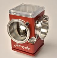
few-cycle offers a beam steering system with 4-axis manual control of the beam path under vacuum. Yaw, pitch, rotation and position adjustments are implemented with a highly stable flexure mount. The device supports optics with diameters up to 3”. Flange type: KF 50. Pressure down to 10−6 mbar.


Schäfter + Kirchhoff
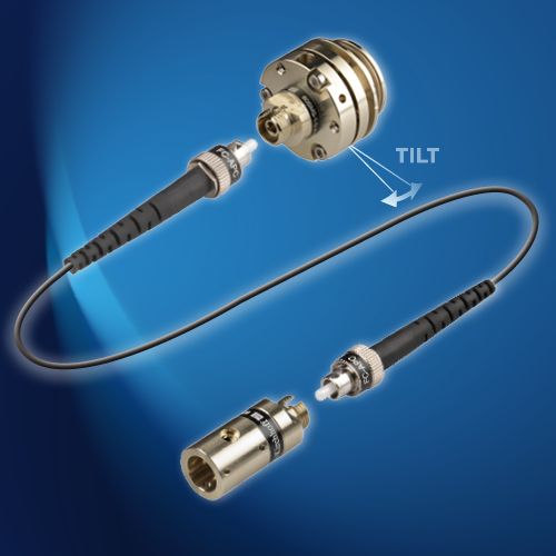
We offer beam delivery systems that consist of a laser beam coupler of series 60SMS, a polarization-maintaining fiber cable and a fiber collimator of series 60FC.


GLOphotonics
GLO hollow-core fiber technology for the ultra-fast laser (femtosecond, picosecond and nanosecond) and high power laser. The beam delivery products cover a large parameter space in laser average power, pulse energy and wavelength (from UV to MIR). Beam delivery product family brings the exceptional hollow-core fiber technology performance in laser energy and power handling and in dispersion management to the widest range of applications and requirements.


art photonics
Our Mid-IR Optical System includes a hollow silica glass waveguides (HWG) cable, which provides flexible delivery of radiation in the mid-IR spectral range (from 2 μm to 18 μm) in the form of weakly divergent beams. HWG cables are free from Fresnel reflection losses at their ends due to their hollow core structure. This advantage and the small numerical aperture (<0.1) of the output beam make HWG preferable for laser power delivery. The flexible beam delivery system for Er:YAG, CO and CO2 lasers includes an adjustable focusing coupler with pilot beam channel and cooling gas inlet – to be fixed on laser head. Output of the cable could be connected with focusing or collimating handpiece.
Questions and Comments from Users
Here you can submit questions and comments. As far as they get accepted by the author, they will appear above this paragraph together with the author’s answer. The author will decide on acceptance based on certain criteria. Essentially, the issue must be of sufficiently broad interest.
Please do not enter personal data here; we would otherwise delete it soon. (See also our privacy declaration.) If you wish to receive personal feedback or consultancy from the author, please contact him, e.g. via e-mail.
By submitting the information, you give your consent to the potential publication of your inputs on our website according to our rules. (If you later retract your consent, we will delete those inputs.) As your inputs are first reviewed by the author, they may be published with some delay.


Share this with your friends and colleagues, e.g. via social media:
These sharing buttons are implemented in a privacy-friendly way!