Tutorial: Fiber Amplifiers
This is part 8 of a tutorial on fiber amplifiers from Dr. Paschotta. The tutorial has the following parts:
2: Gain and pump absorption
3: Self-consistent solutions for the steady state
4: Amplified spontaneous emission
5: Forward and backward pumping
6: Double-clad fibers for high-power operation
7: Fiber amplifiers for nanosecond pulses
8: Fiber amplifiers for ultrashort pulses
9: Noise of fiber amplifiers
10: Multi-stage fiber amplifiers
Part 8: Fiber Amplifiers for Ultrashort Pulses
We now consider the amplification of ultrashort pulses, i.e., light pulses with picosecond or femtosecond durations. Fiber amplifiers are often used for that purpose. They are then sometimes called ultrafast fiber amplifiers, although this term is somewhat vague: strictly speaking, what is fast is only the rise and fall of the optical power of an ultrashort pulse, but not the amplifier.
Attractions of Fibers for Ultrashort Pulse Amplification
In some ways, fiber amplifiers look like the ideal devices for amplifying ultrashort pulses. They offer a high gain and high gain efficiency, as is often required in this area, e.g. when amplifying pulses from some low-energy seed laser to considerable energies in order to reach enormous peak powers. Also, their quite large gain bandwidth allows one to do that even with pretty short pulses, e.g. with pulse durations of 100 fs or even less. Add various general advantages of optical fibers to that, such as the often high power conversion efficiency and the normally quite high beam quality of the generated outputs, and we have an impressive set of advantages.
The Basic Problem: Fiber Nonlinearities
In part 11 of our tutorial Passive Fiber Optics, we have already explained what kind of nonlinearities occur in optical fibers: in particular, the Kerr effect, leading to self-phase modulation, nonlinear self-focusing, parametric amplification and four-wave mixing, and the delayed nonlinear response, leading to stimulated Brillouin scattering (SBS) and Raman scattering (SRS). And in the previous part of this tutorial we have discussed what that means for nanosecond pulse amplification. For ultrashort pulses, the situation is similar, but with some notable differences:
- For the same pulse energy, the peak power is even much higher. This means that generally nonlinear effects become severe already for lower pulse energies.
- As an exception to this, stimulated Brillouin scattering is less of a problem in this regime due to the large intrinsic bandwidth of ultrashort pulses.
- Some nonlinear effects are also mitigated by the group velocity mismatch between different frequency components.
As an example for the group velocity mismatch, if the fiber's group velocity dispersion is 15,000 fs2/m, light produced by SRS with an offset of 13 THz will have an inverse group velocity which differs from that of the original wave by 15,000 fs2/m · <$2\pi$> · 13 THz = 1.23 ps/m. That means that a 1-ps pulse will experience much less SRS in a 10 m long fiber amplifier than one might expect when considering its peak power only. (For self-phase modulation, the chromatic dispersion helps much less, as we have an interaction within a smaller frequency range.)
Generally, the chromatic dispersion of the amplifier fiber has a strong influence of nonlinear effects. It is not only the mentioned group velocity mismatch between totally different wavelength components, but also the dispersion within smaller wavelength regions. For example, in the anomalous dispersion regime (i.e., for negative group velocity dispersion), we can have soliton effects, which sometimes lead to pulse compression and thus even increased peak powers (particularly for injected pulse energies well above the fundamental soliton energy). In the normal dispersion regime, however, we get increased temporal pulse broadening and thus reduced peak powers, so that higher pulse energies become possible without complete pulse break-up. Overall, what happens is often rather complicated, and some easy rules of thumb are not sufficient for understanding what will happen and how severe nonlinear effects will be. Numerical simulations are then required. In the following, we present two example cases.
Example 1: Parabolic Pulse Amplifier
One method to mitigate nonlinear effects in fiber amplifiers is to use parabolic pulse amplification in the normal dispersion regime. Here, wave breaking can be avoided, if the parameters do not get too extreme. For a given gain per unit length, there is an asymptotic solution for the pulses with a parabolic temporal shape. The gain (considered to be constant over the bandwidth of the pulses) determines the growth of pulse energy along the fiber. For each pulse energy, the asymptotic solution sets a certain pulse duration and bandwidth, which both depend on the gain per unit length, the group velocity dispersion and the strength of the Kerr nonlinearity. The latter depends on the nonlinear index and the effective mode area. For the details, see our encyclopedia article on parabolic pulses.
Generally, pulses are not injected into an amplifier such that they already match the asymptotic solution; they then approach that solution more and more during propagation. The exact properties of the input pulses turn out not to be critical, which is a nice feature of this amplification method.
Unfortunately, there is only a limited scope for high pulse energies with parabolic pulses because the gain bandwidth is a limiting factor. As an example, consider an ytterbium-doped fiber amplifier a double-clad fiber (see part 6) with an effective mode area of ≈320 μm2, which is several times more than often used for preamplifiers. Figure 1 shows the result of a simulation, where already chirped pulses from a preamplifier stage enter that double-clad amplifier with an energy of 0.65 nJ and are amplified to 36 nJ.

Power losses in the compressor have been neglected.
The pulse profile is similar to a parabolic one, although the input pulses to the preamplifier were of Gaussian shape. However, the pulses have not fully reached the asymptotic solution.
Figure 2 shows the pulses in the spectral domain. Their bandwidth is of the order of 20 nm, where the limited gain bandwidth starts to have some effects. That happens already for a moderate output pulse energy – far below the multi-microjoule level as required for applications in laser material processing, for example.

Note that the spectral phase has a nearly parabolic shape. This is very convenient, as one can then obtain a flat spectral phase (and thus a strongly reduced pulse duration) with a pulse compressor having only a constant group velocity dispersion over that spectral range.
Remarkably, the compressed pulses do not change much if the input pulse duration to the preamplifier is 2 times higher or lower, or if the input pulses are strongly chirped.
One could push the pulse energy somewhat further, using a large mode area and possibly accepting some reduction in pulse quality. However, one can see that parabolic pulse amplification does not easily scale into the millijoule region.
Example 2: Chirped-pulse Amplifier
For higher pulse energies, one can employ the principle of chirped-pulse amplification (CPA). That means that we apply strong dispersive pulse stretching before the fiber amplifier, and dispersive pulse compression after the amplifier.
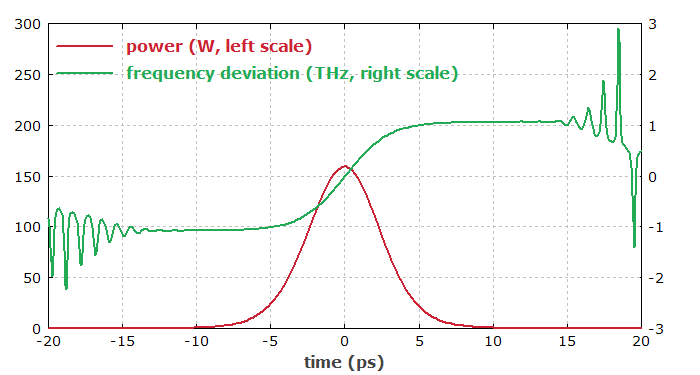
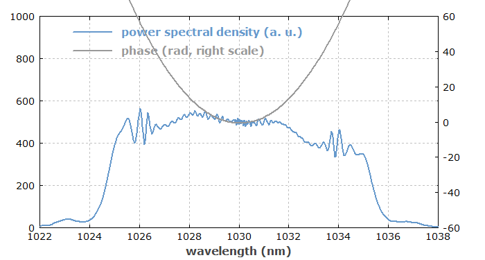
As an example, consider an ytterbium-doped fiber amplifier for 1-nJ seed pulses, having a duration of 5.7 ps (see Figure 3). These pulses have been generated in a dissipative soliton fiber laser, which is subject of a case study for our RP Fiber Power software. The pulses are already up-chirped (see the rising instantaneous frequency) and have a spectral width of 7.6 nm (measured at the 10% level).

Their peak power of 160 W is moderate, but still too high to directly apply a high gain. Therefore, we first use a 100 m long passive fiber as a dispersive pulse stretcher, increasing the pulse duration to 46 ps, so that the peak power drops to 23 W. Note that the initial chirp of the pulses from the laser enhances the broadening; a transform-limited pulse with the same duration would require a much longer fiber length for that broadening.
Figure 4 shows that the instantaneous frequency of the stretched input pulses rises quite linearly with time.

Because the fiber nonlinearity is not negligible, the spectrum is further broadened to a width of 10.4 nm:

Now we inject these pulses into an amplifier fiber with a mode area of 310 μm2, which raises the pulse energy from 1 nJ to 1.55 μJ. That level of pulse energy easily allows the operation with a high pulse repetition rate of e.g. 100 kHz, which leads to an average output power of only 155 mW. The output pulses in the time domain are shown in Figure 6:

The temporal shape has been somewhat distorted, as the influence of fiber nonlinearities is not negligible despite the substantial pulse stretching; the peak power becomes 40 kW at the output. The spectrum is also further distorted, although the spectral phase remains close to parabolic:

Finally, we can employ a dispersive compressor with numerically optimized second- and third-order dispersion. That temporally compresses the pulses to 285 fs. The peak power rises up to 4.8 MW, if energy losses in the compressor are neglected.

The spectral phase of the compressed pulses is quite flat, except in the wings:

Limits for Fiber CPA Systems
One sees that for higher pulse energies one should use stronger pulse stretching in order to limit the peak power in the fiber. The longest practical stretched pulse durations (with a bulky pair of diffraction gratings for compression) are a couple of nanoseconds, which in combination with the self-focusing limit for the peak power (a few megawatts) leads to maximum pulse energies of the order of 10 mJ.
Volume Bragg gratings allow for much more compact setups, but only allow for stretched pulse durations in the picosecond regime. Therefore, the possible pulse energies (combined with reasonable pulse quality) are accordingly lower.
As one will not want to employ a stronger pulse stretching than really necessary, substantial nonlinear effects can still occur in the fiber. Ideally, the pulse compressor should be optimized such that the compression works well despite some nonlinear effects.
Conclusions
Nonlinear effects are the main limiting factor for the performance of ultrafast amplifiers. There are ways to mitigate such effects – we have discussed two techniques, namely parabolic pulse amplification and chirped-pulse amplification. Still, severe limitations remain. For higher pulse energies, bulk amplifiers are superior.
Note, however, that ultrafast fiber amplifiers can be made to operate with very high average output powers, if one limits the pulse energies by using very high pulse repetition rates. In this regime, they are often superior over bulk amplifiers, as they can offer high output powers with no substantial thermal effects, and with an often higher power conversion efficiency.
Obviously, numerical simulations are indispensable for the design of ultrafast amplifiers, as one needs to check various aspects, such as higher-order dispersion, nonlinear distortions, the limited gain bandwidth, gain saturation and ASE.
Go to Part 9: Noise of Fiber Amplifiers or back to the start page.
Questions and Comments from Users
Here you can submit questions and comments. As far as they get accepted by the author, they will appear above this paragraph together with the author’s answer. The author will decide on acceptance based on certain criteria. Essentially, the issue must be of sufficiently broad interest.
Please do not enter personal data here; we would otherwise delete it soon. (See also our privacy declaration.) If you wish to receive personal feedback or consultancy from the author, please contact him, e.g. via e-mail.
By submitting the information, you give your consent to the potential publication of your inputs on our website according to our rules. (If you later retract your consent, we will delete those inputs.) As your inputs are first reviewed by the author, they may be published with some delay.


Connect and share this with your network:
Follow our specific LinkedIn pages for more insights and updates: